If a CNC part lifts when you tighten the vise, the clamping load has changed how the blank sits. CNC vise jaw lift is one possible explanation: the jaws can deflect under force and alter the part's alignment. But a rising corner is an observation, not a complete diagnosis. Debris at a contact, unsuitable support, or a workpiece that bends under the load can also change its seating.
The immediate question is what changed between the resting blank and the secured blank. Establish that relationship before machining. A handle that feels tight does not tell you whether the intended support contacts remain engaged, and changing the work zero cannot repair a mechanical holding problem.
Side Grip Does Not Automatically Mean Downward Seating
A vise applies its holding load through the surfaces contacted by its jaws. The blank may initially rest on a support, but that resting condition is not a guarantee that it will retain the same orientation as the jaws are tightened. The part, contacts and fixture respond together to the load. Judging only how the blank looked before clamping leaves out the state in which it will actually be machined.
Tormach's guide to CNC vises describes jaw deflection under clamping force, including outward movement along the tops of the jaws. If the jaws change alignment against the workpiece, its relationship to the support and cutting plane can change too. That explains why an initially seated part can lift; it does not establish that every seating change comes from jaw deflection or that every vise behaves identically.
The distinction matters for a compact rectangular blank. Firm contact on its sides and dependable contact beneath it perform related but different jobs. The first resists the machining load through the grip. The second helps establish the position and orientation that the setup relies on. Increasing the side load does not, by itself, prove that the intended lower contacts are still doing their job.
For an ED1 setup, the ED1 aluminum vise bench clamp is the dedicated side-gripping accessory. Its relevance is the holding arrangement it provides for suitable blanks—not a promise that an arbitrary part will seat correctly or that the accessory will cure an existing lift problem.
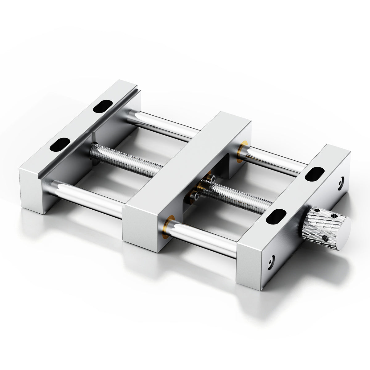
Was the Blank Seated Before the Load Changed?
A part that was never resting on its intended contacts presents a different problem from one that leaves those contacts during tightening. A chip beneath the blank can hold a region above its support before the vise is even secured. An uneven or unsuitable contact arrangement can also leave the blank resting differently from the position the maker intended. Tightening then acts on an already ambiguous starting condition.
Carr Lane's workholding guidance discusses the importance of support and contact, including how chips beneath a part can lift it off its supports. For this diagnosis, the useful principle is straightforward: the visible top surface does not tell the whole story about the interface beneath it. Removing visible debris from the jaws alone is not proof that the intended support contacts are clear.
Physical inspection and cleaning belong in the machine's approved stopped and isolated setup state. Do not reach into a running enclosure or scatter debris with compressed air. The purpose is to restore the intended contacts, not to make the top of the blank merely look level. If the stock or contact arrangement cannot establish those contacts without force, that uncertainty needs resolving before the clamping response is interpreted.
Material response adds another distinction. An entire blank can tilt as a relatively rigid body, while a less rigid region can bend under concentrated holding load. Both may appear as a top-height change at one point. The second is not automatically evidence that the jaw itself moved upward; the workpiece may have changed shape instead. Support and the location of the applied load therefore matter alongside the vise mechanism.
Observe the Part and the Jaw as Separate Questions
A properly mounted indicator can help reveal movement where the exact setup permits this observation. Tormach describes observing the jaw or the workpiece as the vise is tightened. Contacting the workpiece asks what happened to that part at the measured location. Contacting the jaw asks what happened to the hardware at that location. Neither observation should silently stand in for the other.
The reference for the measurement matters too. An indicator reports movement relative to its mounting arrangement, not an absolute diagnosis. If its support or contact changes, the reading no longer represents the same relationship. Use a suitable, stable reference and the procedure appropriate to the actual machine and fixture. There is no universal indicator resolution or acceptable lift value that applies to every desktop CNC job.
One point also cannot describe an entire plane. A corner that rises while a distant region stays at the same height suggests a different change from broadly similar movement across the blank. Local bending can produce another pattern. Comparing meaningful locations can clarify the shape of the movement, but the pattern still needs to be interpreted alongside the physical contacts; it is not an automatic fault code for the vise.
Likewise, a stationary reading on one accessible part of a jaw does not prove that every jaw contact or every part surface stayed unchanged. The useful result is a more specific observation: which part of the arrangement moved, relative to what, and under which holding state. Keep measuring equipment outside the cutting envelope and remove it before machine motion. Hands-on setup must follow the exact machine and accessory isolation instructions.
A Lifted Reference Cannot Be Fixed by Moving the Work Zero
Consider a hypothetical compact blank intended to receive a shallow feature on its top face. This is a geometry example, not a machining trial. While the blank rests on its support, the maker establishes a reference for the top. After the final hold is applied, one end rises while the other remains near its earlier position.
The original reference no longer describes the same relationship between that face and the cutting plane. Resetting Z at one point might make that point agree with the program again, but it does not rotate the physical face back into its intended orientation. A shallow feature extending across the top can encounter a different relationship at the other end. A coordinate change cannot remove the tilt.
A uniform position change would pose a different geometric question, but still would not answer the holding question. Establishing a new reference can describe a stable, accepted final setup; it cannot establish that missing support has returned or that the part will resist the cut. Workholding must be resolved before its location becomes a trustworthy basis for machining.

That relationship is relevant when planning vise work on the ED1 desktop CNC router. The machine provides the machining platform and the vise provides a holding option; the usable setup still depends on the particular blank, support, contacts and tool access. An enclosed machine does not remove the need to establish those relationships.
Correct the Cause Without Trading Away the Hold
More tightening is not a universal correction because it changes the load without necessarily correcting the contact that caused the movement. Reducing force until an indicator stops moving is not a complete answer either: the part must still be retained against the actual machining load. An apparently level blank that can move is not a successful setup.
Adding an unspecified soft layer can change contact and seating rather than simply protect the part. Hammering a blank down or adjusting a screw found on another vise's diagram also assumes a mechanism and procedure that may not apply. General explanations of jaw lift should not be treated as permission to modify the ED1 vise or copy another manufacturer's adjustment method. Use the instructions for the exact hardware; unexplained movement, damage or an uncertain adjustment belongs with appropriate manufacturer support.
Even repeatable movement needs interpretation. A consistent rise does not automatically make the arrangement acceptable, and this article cannot supply a tolerance for an unknown drawing or fixture. The relevant question is whether the final secured state provides the required support, retention and geometric relationship for the intended operation. If those cannot be established, do not use a trial cut to find out whether the blank stays put. Correct the holding arrangement first, then establish the machining reference from that resolved state.