A chamfer mill can sometimes make a countersink, but overlapping capabilities do not make all chamfer mills and countersinks interchangeable. Start with the finished hole: does it need a small edge break, a dimensioned chamfer, or a conical seat for a specified flat-head screw? Then match the exact tool's angle, cutting geometry and permitted operation to that feature.
The distinction matters on a small CNC-machined panel. A comfortable hole lip and a screw seat can look similar from above, yet removing a burr does not necessarily produce the bearing surface a fastener requires. A flush-looking head is not sufficient evidence of correct contact.
Three requirements hiding behind a sloped edge
Deburring removes unwanted material left by a previous operation. An edge break removes the sharp intersection between surfaces; it may be specified as a small chamfer, but it is not automatically a fastener feature. A dimensioned chamfer has a defined geometric requirement, while a countersunk fastener seat must agree with the mating head and the part drawing.
A countersink is conical. A counterbore, by contrast, is a cylindrical recess with a flat bottom. Both may recess a fastener head, but they accommodate different head geometries. “I want the screw below the surface” is therefore not a complete tool specification.
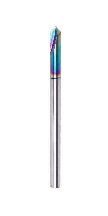
A chamfer mill is often versatile. Harvey Performance's discussion of chamfer mills describes edge chamfering, beveling, deburring and some countersinking applications. It also distinguishes pointed cutters from tipped-off, non-center-cutting geometry. The useful lesson is to read the exact tool drawing and application data, not to assume that every tapered cutter can perform every operation.
The screw specification decides the seat angle
The included angle is measured across the full cone. It is not the half-angle between one side and the centerline. For example, a 90-degree included cone has sides at 45 degrees to its axis. Check the convention used on the cutter drawing as well as the fastener drawing; a label such as “45-degree chamfer tool” can otherwise be misread.
Severance's countersink-angle guide explains the included-angle convention and common 82-, 90- and 100-degree applications. These associations are useful orientation, not permission to infer every screw's head angle from its thread system or country of origin. Use the actual fastener specification and the part's countersink callout.
If the angles differ, altering depth may change how the head looks without making the two conical surfaces match. The head can contact a narrow region instead of the intended seat. Cutting deeper to hide the head can also enlarge the recess and reduce remaining material. Stop treating appearance as the deciding measurement.
For a decorative edge break with no mating cone, the design may allow a different angle. That freedom belongs to the feature's requirements; it does not transfer to a hole intended for a specified fastener.
Compare the cutting envelope, not just the angle
A correct angle is necessary for a specified conical seat, but it is not sufficient. The cone must cover the required diameters, and the complete tool must reach the hole without unwanted contact. A truncated tip, a noncutting nose, limited cutting length, or a nearby wall can change the usable range.
In a concentric axial countersinking move, ask whether the existing hole clears the nose and whether the usable cutting edges extend from that opening to the intended outer diameter. Do not assume a small hole will admit a large noncutting tip. An interpolated chamfer path presents a different engagement problem; it is an option only when the exact cutter and application support it, not an automatic workaround for unsuitable geometry.
Tool-family names are not a substitute for these checks. For example, RUKO's cross-hole countersink product page includes an explicit limitation concerning full countersinking. That illustrates why a countersink label alone cannot establish suitability for every seat. It is not a recommendation to transfer that product's material ratings or operating conditions to a different tool.
Consider the maximum occupied space as well as the active edge. A cutter may reach the intended cone while its wider body, shank or holder threatens an adjacent pocket wall. The toolpath preview should reflect the actual tool definition and remaining stock, rather than showing only an ideal sharp point.
Choose differently for three holes in one panel
Consider a hypothetical aluminum control panel made on a desktop CNC router. One through-hole needs a comfortable handling edge, another receives a specified flat-head screw, and a third lies beside a raised pocket wall. This is a selection example, not a tested part or a set of cutting instructions.
At the handling hole, the purpose is simply to remove the unwanted sharp lip within the design's allowed edge treatment. A suitable chamfer mill can be useful without forming a full screw seat. Making a broad, attractive cone would remove material the feature does not need to lose.
At the fastener hole, begin with the screw's head geometry and the required seat dimensions. A dedicated countersink may suit the operation; a chamfer mill may also suit it if its documented angle, usable cone and application agree. Versatility is valuable only after those requirements are satisfied.
At the hole beside the wall, access can overrule an otherwise reasonable tool choice. A smaller suitable cutting envelope, another supported approach, or a permitted design change may be necessary. A matching angle does not make the holder pass through the wall, and a more elaborate CAM path cannot make a noncutting surface into a cutting edge.
When browsing CNC router bits and end mills, use this feature-level decision to narrow the tools. For CNC router bits for aluminum, confirm the exact cutter's material guidance rather than relying on a carbide label or the fact that a similarly shaped V-bit is used for wooden lettering. Shank, collet, permitted spindle conditions and clearance still have to match the installed setup.
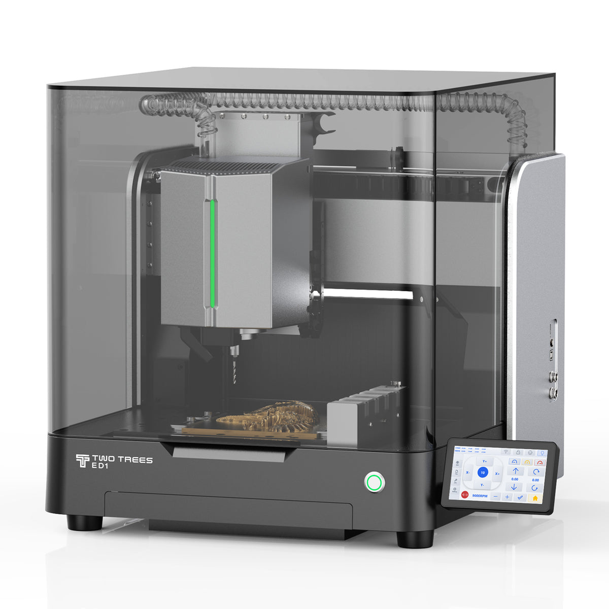
For a panel planned on the ED1 enclosed desktop CNC router, treat the hole-making tool and finishing tool as separate application decisions. A tool guide's chamfer-bit label provides a starting point for checking documentation; it does not qualify a screw seat or supply a universal depth, feed or spindle speed.
Inspect the intended feature before repeating it
Use the machine and tool manufacturer's instructions for setup, cutting conditions, workholding, extraction and protection. Stop and safely isolate the equipment before hands-on inspection, adjustments or tool changes. Do not inspect a seat with a screw while the spindle is moving.
After an appropriately planned first feature, inspect the actual result against its requirement. For an edge break, check that unwanted sharpness is removed without excessive enlargement. For a screw seat, check the specified angle and dimensions and the intended mating contact, not simply whether the head disappears below the face. One acceptable sample is not certification of every later hole or of the assembly's strength.
The panel decision is now specific: edge-break the handling hole, form a matching conical seat only where the fastener calls for one, and choose an envelope that clears the nearby wall. If the required angle or tool geometry is unknown, obtain that information before cutting. A different category name cannot fill the gap.